GATE EC Electromagnetics Previous Year Questions with Solutions
20 Electromagnetics questions from the GATE EC 2026 and 2025 and 2024 and 2023 papers, newest first. Try each one, then open its answer: the official answer from that year's key and a worked solution. Each question links to its place in the full paper.
GATE 2026, Q.21
Electromagnetics1 markMCQ
Using Friis' equation with , m, dBm and dBm, find the distance in km.
Full question on page 21 of the official paper (PDF)
Show answerHide answer
Key idea: A 100 dB path loss is a power ratio of 10^{-10}.
Official answer: B
Here P_R/P_T is -90 - 10 = -100 dB. Set the Friis ratio equal to it:
Option (B).
Learn the idea:
GATE 2026, Q.24
Electromagnetics1 markMCQ
A plane wave in a lossless medium has . What is its polarization?
Full question on page 24 of the official paper (PDF)
Show answerHide answer
Key idea: Equal amplitudes 90 degrees apart give circular polarization; the rotation sense fixes the hand.
Official answer: A
At z = 0 the field points along \hat{x} at t = 0 and along \hat{y} a quarter period later, with the same magnitude: it is circular, turning from x towards y.
The wave travels along +z. With the right thumb along +z, the fingers curl from x to y, so the wave is right-handed circularly polarized (IEEE convention). Option (A).
GATE 2026, Q.28
Electromagnetics1 markMSQ
Which expressions describe the dielectric loss tangent of a substrate?
One or more options are correct.
Full question on page 28 of the official paper (PDF)
Show answerHide answer
Key idea: The loss tangent is the in-phase (lossy) current over the quadrature current.
Official answer: A and B
With \epsilon = \epsilon' - j\epsilon'' and conductivity \sigma, Ampère's law gives the total current density
The loss tangent is the ratio of the in-phase (lossy) part to the quadrature part:
\tan\delta = \frac{\omega\epsilon'' + \sigma}{\omega\epsilon'}That is option (B), and option (A) describes the same ratio in words. Susceptibility over permittivity (C) and P over D (D) measure how polarizable the material is, not its loss.
Learn the idea:
GATE 2026, Q.33
Electromagnetics1 markNAT
Find the cutoff frequency of the TE10 mode in an air-filled rectangular waveguide of 0.28 inch by 0.14 inch.
Answer format: GHz, rounded off to two decimal places
Full question on page 31 of the official paper (PDF)
Show answerHide answer
Key idea: f_c = c/(2a) with a the broad dimension.
Official answer: 20.50 to 21.50
GATE 2026, Q.34
Electromagnetics1 markNAT
and cross at dB for a lossless two-port and at dB for a lossy one. What percentage of the incident power does the lossy network dissipate at the crossing?
Answer format: Percent, rounded off to two decimal places
Full question on page 31 of the official paper (PDF)
Show answerHide answer
Key idea: Power lost inside is 1 - |S_{11}|^2 - |S_{21}|^2.
Official answer: 20.00 to 21.00
At the crossing both magnitudes are -4 dB:
About 20.38% is dissipated. (For the lossless network, 2 \times 10^{-0.3} \approx 1, as it should be.)
Learn the idea:
GATE 2026, Q.52
Electromagnetics2 marksMCQ
A load has on a 50 Ω coaxial cable. Its input impedance moves to the diametrically opposite point on the same circle. Find the nearest input impedance.
Full question on page 49 of the official paper (PDF)
Show answerHide answer
Key idea: The opposite point has \Gamma_{in} = -\Gamma_L; then Z = 50\,\frac{1+\Gamma}{1-\Gamma}.
Official answer: B
Rotate \Gamma_L by 180° (a quarter wavelength of line):
Option (B). The load itself is Z_L \approx 97.7 + j65.1 Ω (close to option (D)), and the two satisfy Z_{in}Z_L = 50^2, as a quarter-wave line requires.
Learn the idea:
GATE 2025, Q.49
Electromagnetics2 marksMCQ
A 4 m × 4 m metal sheet lies in the - plane with corners at , as in the figure. Its surface charge density is µC/m². What is the total charge on the sheet, in µC?
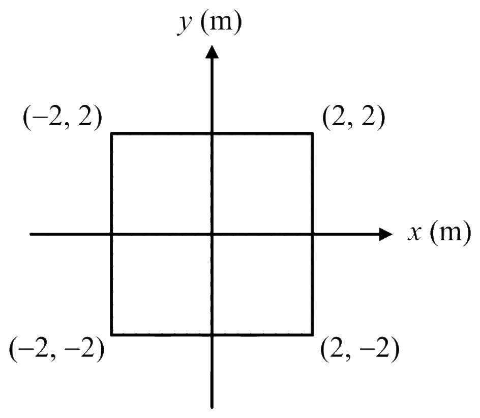
Full question on page 44 of the official paper (PDF)
Show answerHide answer
Key idea: Integrate the density over the area; the absolute value doubles the half where y > 0.
Official answer: C
Option (C). Dropping the absolute value would make the two halves cancel to 0, and 16 is the total without the factor of 4.
Learn the idea:
GATE 2025, Q.50
Electromagnetics2 marksMCQ
A field of 0.01 V/m is applied along a copper wire of circular cross-section, 1 mm in diameter. Copper's conductivity is S/m. What current flows, in amperes, to two decimal places?
Full question on page 45 of the official paper (PDF)
Show answerHide answer
Key idea: Ohm's law in point form, J = \sigma E, times the cross-sectional area gives the current.
Official answer: A
To two decimal places, 0.46 A. Option (A). Using the 1 mm diameter as the radius gives 1.82, option (B).
Learn the idea:
GATE 2025, Q.64
Electromagnetics2 marksNAT
A 50 Ω lossless transmission line is terminated in Ω. If the average incident power is 10 mW, what average power reaches the load, in mW?
Answer format: mW, rounded off to one decimal place
Full question on page 52 of the official paper (PDF)
Show answerHide answer
Key idea: On a lossless line the load gets the incident power minus the reflected power, 1 - |\Gamma|^2 of it.
Official answer: 6.30 to 6.50
Learn the idea:
GATE 2025, Q.65
Electromagnetics2 marksNAT
A loop of area 5 m² in the - plane contains two 2 Ω resistors in series, as in the figure. A flux density T is applied along the positive -axis. What is the magnitude of the current in the loop, in amperes?
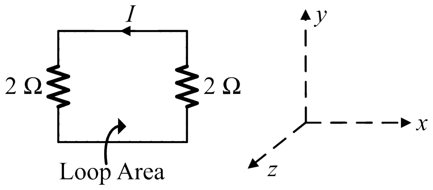
Answer format: Amperes, rounded off to two decimal places
Full question on page 52 of the official paper (PDF)
Show answerHide answer
Key idea: The induced EMF is the rate of change of flux through the loop, and it drives current through the loop's total resistance.
Official answer: 0.62 to 0.63
The key accepts 0.62 to 0.63, either rounding of 0.625. Using one resistor instead of both gives 1.25 A.
GATE 2024, Q.15
Electromagnetics1 markMCQ
A lossless line is short-circuited at , as in the figure. Moving towards the generator, the points A, B, C and D are , , and from the load. What are the normalised input impedances , , and ?
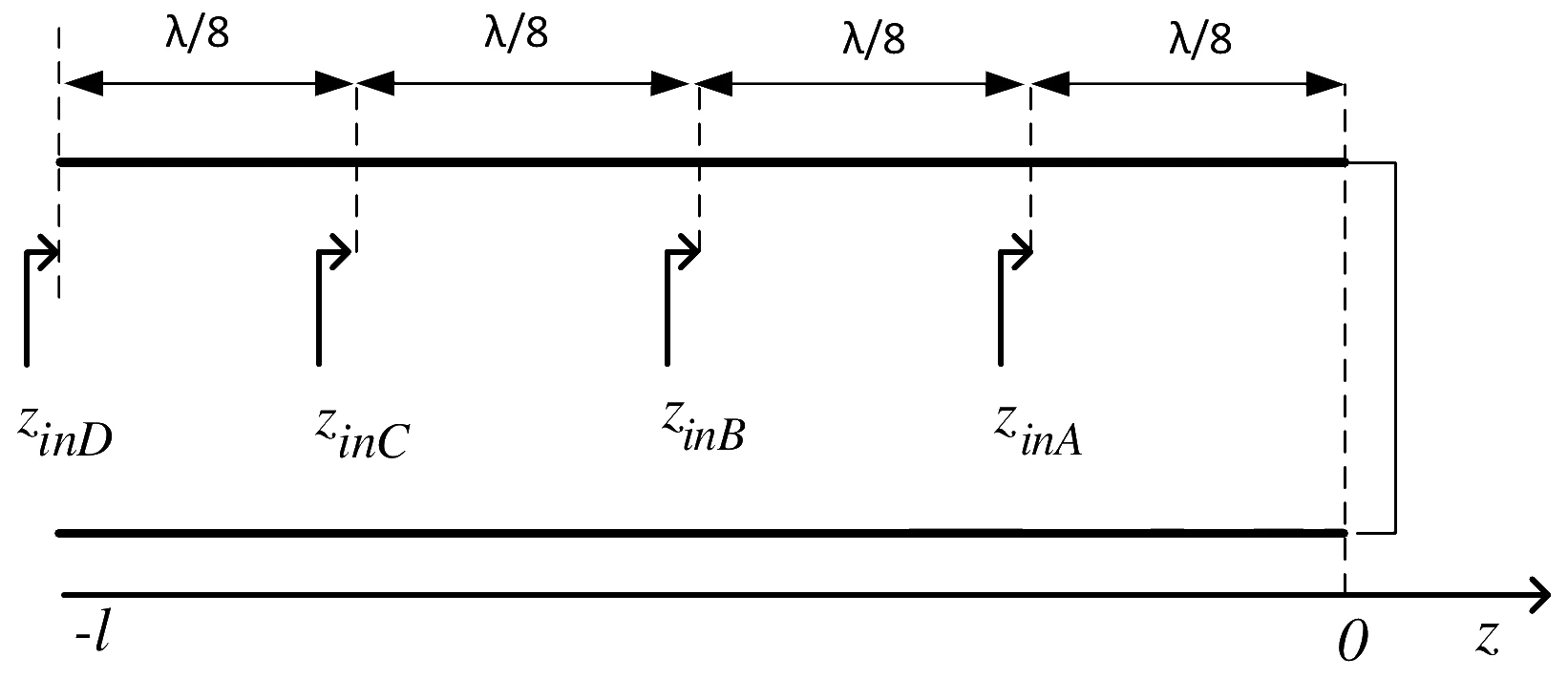
Full question on page 13 of the official paper (PDF)
Show answerHide answer
Key idea: A shorted lossless line of length l has normalised input impedance j\tan\beta l.
Official answer: A
With \beta = 2\pi/\lambda, each \lambda/8 step adds 45° to \beta l:
- A, \lambda/8: j\tan 45° = +j1
- B, \lambda/4: j\tan 90° = \infty (an open circuit)
- C, 3\lambda/8: j\tan 135° = -j1
- D, \lambda/2: j\tan 180° = 0 (a short again)
Option (A).
Learn the idea:
GATE 2024, Q.16
Electromagnetics1 markMCQ
With and the unit vectors along and and a positive constant, which statement is true of and ?
Full question on page 14 of the official paper (PDF)
Show answerHide answer
Key idea: An electrostatic field is the gradient of a potential, so its curl must be zero.
Official answer: B
Only \mathbf{F}_1 is curl-free; it is -\nabla V for V = -Axy. Option (B).
Learn the idea:
GATE 2024, Q.39
Electromagnetics2 marksMCQ
A uniform plane wave V/m travels in air in the direction and is incident normally on a perfect electric conductor at . Where is the first null of the total magnetic field in the air, measured from , in metres?
Full question on page 30 of the official paper (PDF)
Show answerHide answer
Key idea: At a perfect conductor the electric field has a null and the magnetic field a maximum, so the magnetic nulls are a quarter wavelength away.
Official answer: A
From the exponent, \beta = 2\pi/3 rad/m, so \lambda = 2\pi/\beta = 3 m. The reflected wave makes a standing wave with
E \propto \sin\beta x, \qquad H \propto \cos\beta xH is largest at the conductor and first vanishes where \beta x = -\pi/2, at x = -\lambda/4 = -0.75 m. Option (A). The electric field's first null in the air is at -\lambda/2 = -1.5 m, option (B).
Learn the idea:
GATE 2024, Q.58
Electromagnetics2 marksNAT
A lossless line with Ω has an unknown load with . Moving towards the generator, what is the maximum magnitude of the input impedance looking towards the load, in ohms?
Answer format: Ohms
Full question on page 44 of the official paper (PDF)
Show answerHide answer
Key idea: At a voltage maximum the input impedance is purely real and equal to Z_0 times the VSWR.
Official answer: 200
Learn the idea:
GATE 2023, Q.20
Electromagnetics1 markMCQ
A narrow-band signal propagates in a lossless dielectric medium (, ) with phase velocity and group velocity . Which statement is true? ( is the velocity of light in vacuum.)
Full question on page 14 of the official paper (PDF)
Show answerHide answer
Key idea: A lossless dielectric with constant \varepsilon_r is not dispersive, so v_g = v_p.
Official answer: D
v_p = \frac{\omega}{\beta} = \frac{c}{\sqrt{\mu_r \varepsilon_r}} = \frac{c}{2}\beta = \omega\sqrt{\mu\varepsilon} is proportional to \omega, so v_g = d\omega/d\beta is also c/2. Both are less than c. Option (D).
GATE 2023, Q.51
Electromagnetics2 marksMCQ
The S-parameters of a two-port network are , with reference to . Two lossless transmission line sections of electrical lengths and are added to the input and output ports, respectively. What are the S-parameters of the resulting two-port?
Full question on page 37 of the official paper (PDF)
Show answerHide answer
Key idea: Each pass along a lossless line delays a wave by its electrical length, a factor e^{-j\theta}.
Official answer: A
A wave reflected at port 1 crosses the input line twice, in and back out: S'_{11} = S_{11}e^{-j2\theta_1}. Likewise S'_{22} = S_{22}e^{-j2\theta_2}.
A wave passing through crosses both lines once each: S'_{21} = S_{21}e^{-j(\theta_1 + \theta_2)}, and the same for S'_{12}. Every factor is a delay, so every exponent is negative. Option (A).
Learn the idea:
GATE 2023, Q.52
Electromagnetics2 marksMSQ
The standing wave ratio on a 50 Ω lossless line terminated in an unknown load is 2.0. Successive voltage minima are 30 cm apart, and the first minimum is 10 cm from the load. can be replaced by an equivalent length of the same line terminated in a resistance . What are and ?
One or more options are correct.
Full question on page 38 of the official paper (PDF)
Show answerHide answer
Key idea: The impedance is purely resistive at every voltage minimum (Z_0/S) and maximum (Z_0 S), and these repeat every \lambda/2, so the line can be extended past the load to one of them.
Official answer: B and C
Minima are \lambda/2 apart, so \lambda = 60 cm. At a voltage minimum the line looks like Z_0/S = 25 Ω, and at a maximum like Z_0 S = 100 Ω. The load is then the input impedance of a length l_m of line ending in that resistance, measured from the load away from the generator.
- Minima sit at 10 cm, 40 cm, ... towards the generator, so also at 10 - 30 = -20 cm, 20 cm beyond the load: R_m = 25 Ω with l_m = 20 cm.
- Maxima sit \lambda/4 = 15 cm from each minimum, at 25 cm and at -5 cm, 5 cm beyond the load: R_m = 100 Ω with l_m = 5 cm.
Options (B) and (C).
Learn the idea:
GATE 2023, Q.53
Electromagnetics2 marksMSQ
The electric field of a plane wave is V/m. Which combination(s) give a left-handed elliptically polarised (LHEP) wave?
One or more options are correct.
Full question on page 39 of the official paper (PDF)
Show answerHide answer
Key idea: The wave travels along +z; when E_y leads E_x (0 < \theta < \pi), the field turns from +x towards -y, left-handed about +z.
Official answer: A, B and D
At z = 0, take \theta = \pi/2: E_x = C_{1x}\cos\omega t and E_y = -C_{1y}\sin\omega t. As t grows from 0, \mathbf{E} moves from +x towards -y: clockwise as seen looking along +z, opposite to the right-hand rule about the direction of travel. That is left-handed, and the same holds for any 0 < \theta < \pi, since the sign of \sin\theta sets the sense. \pi < \theta < 2\pi gives right-handed.
- (A) \theta = \pi/4: left-handed, and elliptical (equal amplitudes, but \theta \neq \pi/2). Valid.
- (B) \theta = \pi/2 with unequal amplitudes: left-handed elliptical. Valid.
- (C) \theta = 3\pi/2: right-handed. Not valid.
- (D) \theta = 3\pi/4: left-handed elliptical. Valid.
Options (A), (B) and (D). This uses the IEEE convention, in which handedness is judged looking along the direction of travel.
GATE 2023, Q.54
Electromagnetics2 marksMSQ
Which of the circuits in the figure represent a lumped-element equivalent of an infinitesimal section of a transmission line?
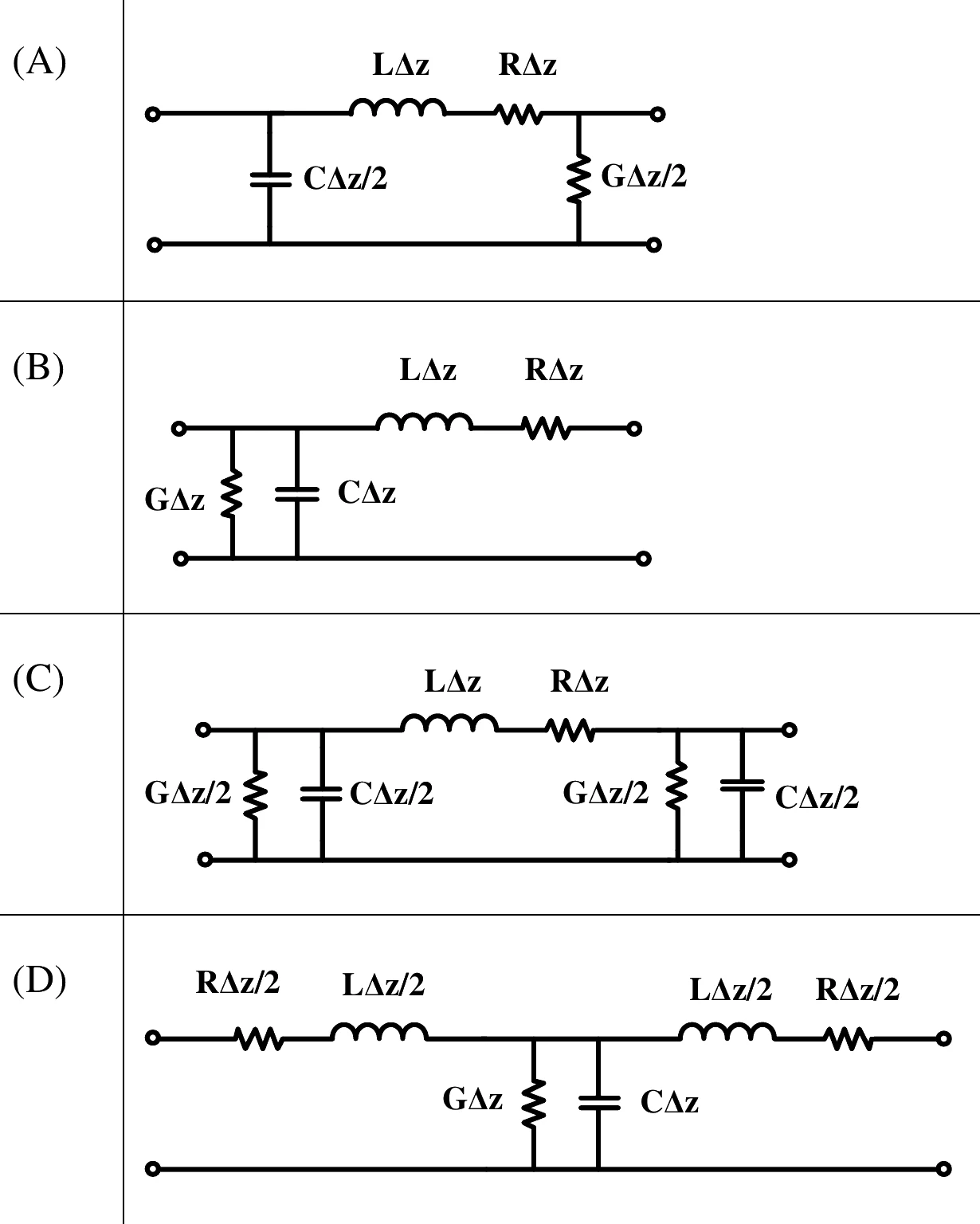
One or more options are correct.
Full question on page 40 of the official paper (PDF)
Show answerHide answer
Key idea: A section of length \Delta z must contain the full series R\Delta z, L\Delta z and the full shunt G\Delta z, C\Delta z, however they are split.
Official answer: B, C and D
As \Delta z \to 0, it doesn't matter where the shunt elements sit (an L, \pi or T section all reduce to the telegrapher's equations), but the totals must be R\Delta z, L\Delta z, G\Delta z and C\Delta z.
- (A) has only C\Delta z/2 and G\Delta z/2 in total: half the shunt elements. Not valid.
- (B) is an L section with the full shunt elements. Valid.
- (C) is a \pi section: two halves of each shunt element. Valid.
- (D) is a T section: two halves of each series element. Valid.
Options (B), (C) and (D).
GATE 2023, Q.60
Electromagnetics2 marksNAT
A transparent dielectric coating is applied to glass (, ) to eliminate the reflection of red light ( µm). What is the minimum thickness of the coating, in µm?
Answer format: µm, rounded off to two decimal places
Full question on page 42 of the official paper (PDF)
Show answerHide answer
Key idea: A quarter-wave layer cancels reflection when its index is the geometric mean of the media on either side.
Official answer: 0.12 to 0.14
Glass has n = \sqrt{4} = 2 and air n = 1, so the coating needs n_c = \sqrt{1 \times 2} = \sqrt{2} and a thickness of a quarter wavelength in the coating:
Answer: 0.13 µm.