GATE EC Networks, Signals and Systems Previous Year Questions with Solutions
46 Networks, Signals and Systems questions from the GATE EC 2026 and 2025 and 2024 and 2023 papers, newest first. Try each one, then open its answer: the official answer from that year's key and a worked solution. Each question links to its place in the full paper.
GATE 2026, Q.13
Networks, Signals and Systems1 markMCQ
Find the Laplace transform of , where is convolution.
Full question on page 13 of the official paper (PDF)
Show answerHide answer
Key idea: Convolution in time is multiplication of Laplace transforms.
Official answer: D
Transform each factor and multiply:
Option (D).
Learn the idea:
GATE 2026, Q.15
Networks, Signals and Systems1 markMCQ
and , for , are both sampled at Hz. Compare their first ten samples.
Full question on page 15 of the official paper (PDF)
Show answerHide answer
Key idea: 50 Hz sampled at 40 Hz aliases onto 10 Hz.
Official answer: D
At F_s = 40 Hz, the sample times are t = n/40:
The 50 Hz signal aliases onto 10 Hz, so every sample is identical. Option (D) is the only statement that holds; (A), (B) and (C) all need one set of samples to be greater.
GATE 2026, Q.16
Networks, Signals and Systems1 markMCQ
A system obeys , with input . Describe the response .
Full question on page 16 of the official paper (PDF)
Show answerHide answer
Key idea: The input's zero cancels one of the system's poles.
Official answer: A
The input cancels the pole at 1/3. The response starts at n = 0 (causal) and decays (stable). Option (A).
Learn the idea:
GATE 2026, Q.23
Networks, Signals and Systems1 markMCQ
A circuit obeys and is driven by , with . Which source-free problem is equivalent?
Full question on page 23 of the official paper (PDF)
Show answerHide answer
Key idea: An impulse of current delivers its charge instantly, so it only shifts the initial voltage.
Official answer: A
Integrate the equation across t = 0. The impulse delivers charge q in zero time, while m(t) (finite) contributes nothing over an instant:
After that, C\,dV/dt = -m(t). So the impulse is equivalent to starting the source-free equation from V_0 + q/C. Option (A), which writes this initial value at t = 0^- for the equivalent problem.
Learn the idea:
GATE 2026, Q.30
Networks, Signals and Systems1 markNAT
A 1 mA source feeds two parallel branches, each of two 1 kΩ resistors in series, and a 6 V battery joins the two branch midpoints. Find the output voltage across the source.
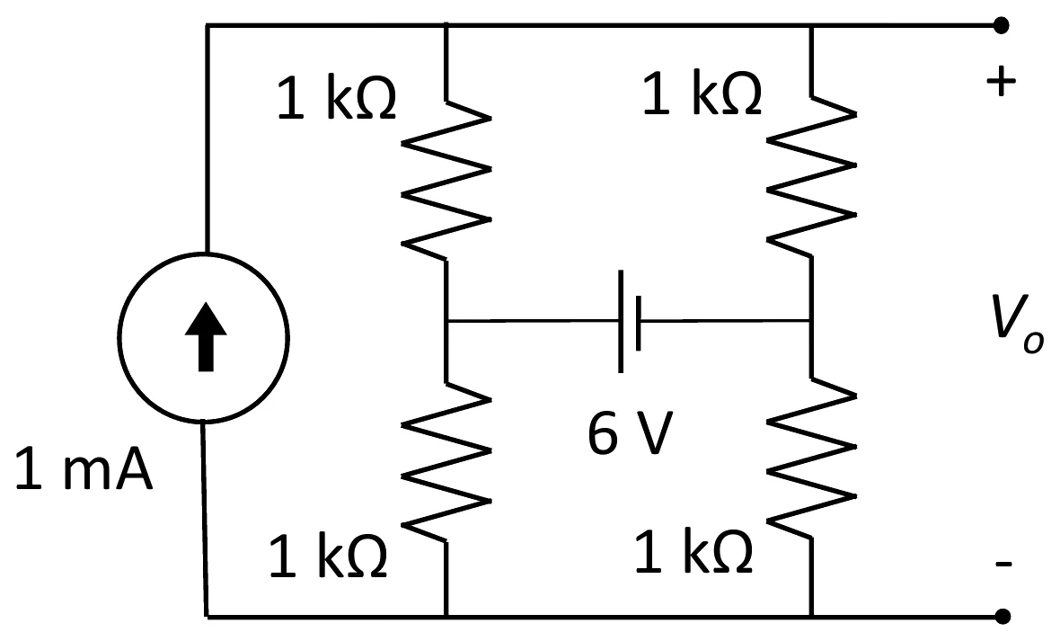
Answer format: Volts, rounded off to two decimal places
Full question on page 30 of the official paper (PDF)
Show answerHide answer
Key idea: The battery's current leaves one midpoint and enters the other, so it cancels from the sum of the node equations.
Official answer: 0.95 to 1.05
Let the bottom rail be 0 V, the top rail T, and the midpoints L and R (volts, kΩ, mA). Whatever current i the battery carries leaves one midpoint and enters the other, so it cancels when the two midpoint equations are added:
At the top rail, the source current leaves through the two upper resistors:
So V_o = 1.00 V, whatever the battery voltage.
Learn the idea:
GATE 2026, Q.31
Networks, Signals and Systems1 markNAT
A source V drives 1 µF, 2.2 mH and 1 kΩ, all in parallel across it. Find the average power in the 1 kΩ resistor at resonance.
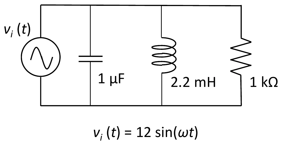
Answer format: Milliwatts, rounded off to two decimal places
Full question on page 31 of the official paper (PDF)
Show answerHide answer
Key idea: The resistor sits directly across the ideal source, so resonance doesn't change its voltage.
Official answer: 71.50 to 72.50
The resistor sees the full 12 V peak, so
Resonance only makes the L and C currents cancel; it doesn't change the resistor's voltage.
Learn the idea:
GATE 2026, Q.37
Networks, Signals and Systems2 marksMCQ
A real periodic signal with period and Fourier coefficients satisfies . For any integer , which is correct?
Full question on page 34 of the official paper (PDF)
Show answerHide answer
Key idea: Half-wave symmetry removes the even harmonics.
Official answer: A
A shift by T/2 multiplies the nth coefficient by e^{-j\pi n} = (-1)^n. The condition x(t - T/2) = -x(t) then says, coefficient by coefficient,
For even n the bracket is 2, so a_{2m} = 0. This is half-wave symmetry: only odd harmonics survive. Option (A).
Learn the idea:
GATE 2026, Q.39
Networks, Signals and Systems2 marksMCQ
An - branch and an - branch ( µH, µF) are in parallel across . At 159.15 kHz their currents are apart (). Find the nearest integer to .
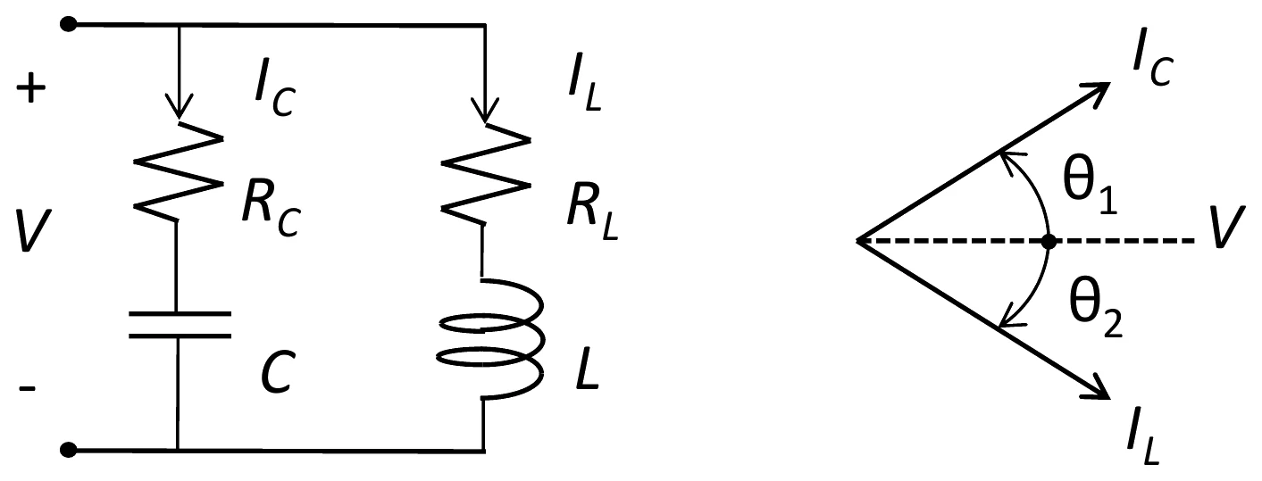
Full question on page 36 of the official paper (PDF)
Show answerHide answer
Key idea: Two angles add to 90^\circ when the product of their tangents is 1.
Official answer: B
At 159.15 kHz, \omega = 2\pi f = 10^6 rad/s, so both reactances are 1 Ω:
I_C leads V by \theta_1 and I_L lags it by \theta_2, with
Two angles add to 90° exactly when the product of their tangents is 1:
Option (B).
Learn the idea:
GATE 2026, Q.43
Networks, Signals and Systems2 marksMCQ
for and 0 elsewhere. Find the ratio of the energy of to the energy of .
Full question on page 40 of the official paper (PDF)
Show answerHide answer
Key idea: Energy goes with the square of the amplitude and with the duration; shifting or reversing a signal leaves it unchanged.
Official answer: C
E[x] = \int_0^1 2^2\,dt = 4Scaling the amplitude by 3 multiplies the energy by 9. Compressing time by a factor of 3 divides it by 3. Shifting and reversing don't change it:
The ratio is 4/12 = 1/3. Option (C).
Learn the idea:
GATE 2026, Q.46
Networks, Signals and Systems2 marksMCQ
For , , 99% of the energy lies within Hz. Which is true of ?
Full question on page 43 of the official paper (PDF)
Show answerHide answer
Key idea: Integrate |X(f)|^2 from -B to B and set it to 99% of the total energy.
Official answer: B
The total energy is \int_0^\infty e^{-4t}\,dt = \tfrac{1}{4}. The energy in -B < f < B is
As a fraction of the total, that is \tfrac{2}{\pi}\tan^{-1}(\pi B). Setting it to 0.99:
So B \approx 63.66/\pi \approx 20.3 Hz, between 63/\pi and 64/\pi. Option (B).
GATE 2026, Q.47
Networks, Signals and Systems2 marksMCQ
A system S is built from two LTI subsystems and , two adders and two unit delays, as in the figure. Which statement is necessarily true?
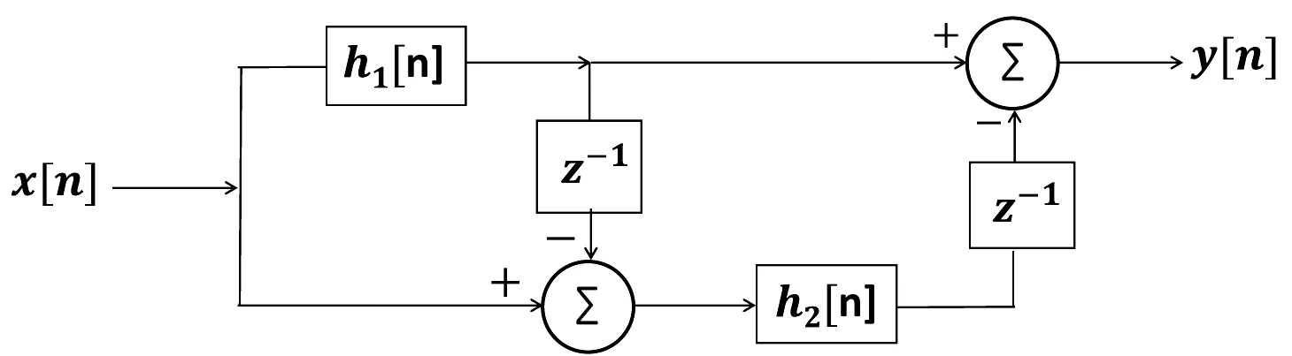
Full question on page 44 of the official paper (PDF)
Show answerHide answer
Key idea: Any interconnection of LTI blocks is LTI, but causality depends on the blocks.
Official answer: B
Reading the figure, the output is
Every block (the two subsystems, the delays and the adders) is linear and time invariant, and any interconnection of LTI blocks is LTI. In the z-domain the whole system is a single transfer function:
So (B) holds, and (C) and (D) are false. Causality (A) isn't guaranteed: nothing says h_1[n] or h_2[n] is zero for n < 0, and if h_1[n] isn't, neither is the overall impulse response. Option (B).
Learn the idea:
GATE 2026, Q.51
Networks, Signals and Systems2 marksMCQ
Find the ABCD parameters of a T network with 1 kΩ in each series arm and 1 kΩ in the shunt arm.
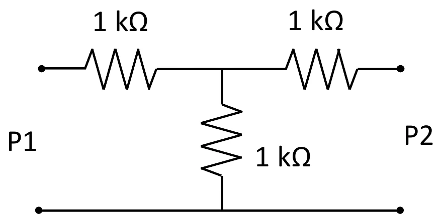
Full question on page 48 of the official paper (PDF)
Show answerHide answer
Key idea: Find A and C with the output open, and B and D with it shorted.
Official answer: D
For a T network with series arms Z_1, Z_2 and shunt arm Z_3:
With all three at 1 kΩ: A = D = 2, B = 3 \times 10^3 Ω and C = 10^{-3} Ω⁻¹. As a check, AD - BC = 4 - 3 = 1, as it must be for a reciprocal network. Option (D).
Learn the idea:
GATE 2026, Q.58
Networks, Signals and Systems2 marksMSQ
Let and for a positive integer . Which statements are valid?
One or more options are correct.
Full question on page 55 of the official paper (PDF)
Show answerHide answer
Key idea: x_2 is at twice x_1's frequency; orthogonality depends on the interval you integrate over.
Official answer: A, C and D
x_1 has frequency n and x_2 has frequency 2n. Multiply them with the product-to-sum identity
2\sin a\cos b = \sin(a+b) + \sin(a-b)and the product is
- Over 0 \le t < 1/n, both sines run through whole cycles, so the inner product is 0: orthogonal. True, (A).
- Orthonormal also needs unit energy, but \int_0^{1/n}\cos^2(2\pi nt)\,dt = 1/(2n), which is never 1 for a positive integer n (and x_2's energy is 2/n). False, (B).
- x_2's frequency 2n is twice x_1's, so x_2 is the second harmonic of x_1. True, (C).
- Over 0 \le t < 1/(2n), \sin(6\pi nt) runs through 1.5 cycles and \sin(2\pi nt) through half a cycle, so neither integral cancels:
So they are not orthogonal over that interval. True, (D). Options (A), (C) and (D).
Note: Option (C) uses harmonic in its usual sense: a sinusoid at a whole-number multiple of a fundamental frequency. Here x_2, at 2n, is the second harmonic of the fundamental n of x_1, so the key includes (C).
Learn the idea:
GATE 2025, Q.17
Networks, Signals and Systems1 markMCQ
In the figure, passes through an LTI subsystem with impulse response , then is added, then it passes through an LTI subsystem , and is subtracted to give , with . If , the overall system is
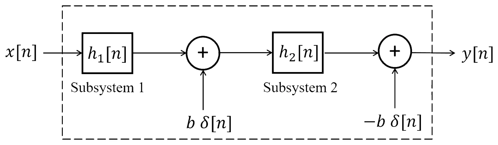
Full question on page 16 of the official paper (PDF)
Show answerHide answer
Key idea: An output term that doesn't depend on the input breaks linearity, and one fixed at n = 0 breaks time invariance.
Official answer: D
Follow a signal through the box:
The second term is the same for every input, and it is not zero because h_2[n] \neq \delta[n]. A zero input therefore gives a non-zero output, so the system is not linear.
That term also stays put at n = 0 when the input is delayed, so a delayed input doesn't give a delayed output: the system is time variant. Option (D). (If h_2[n] = \delta[n], the two b\,\delta[n] terms would cancel and the system would be LTI.)
GATE 2025, Q.18
Networks, Signals and Systems1 markMCQ
is a real continuous-time signal whose Fourier transform exists. Which statement is always TRUE?
Full question on page 17 of the official paper (PDF)
Show answerHide answer
Key idea: The magnitude of an integral is at most the integral of the magnitude.
Official answer: A
Since |e^{-j\omega t}| = 1,
So (A) holds for every f, and (B) never does. (C) and (D) compare with the signed integral, which can fail either way:
- (C) fails for f(t) = -1 on |t| < \tfrac{1}{2}: |F(0)| = 1 but \int f\,dt = -1.
- (D) fails for f(t) = 1 on |t| < \tfrac{1}{2}: at \omega = \pi, |F| = 2/\pi \approx 0.64 < 1.
Option (A).
Learn the idea:
GATE 2025, Q.19
Networks, Signals and Systems1 markMCQ
In the network in the figure, 1 A flows through the 3 Ω resistor from the 9 V node into the junction. Node X is joined to an 8 V node through 2 Ω and to that junction through 1 Ω. What is the voltage at X, in volts?
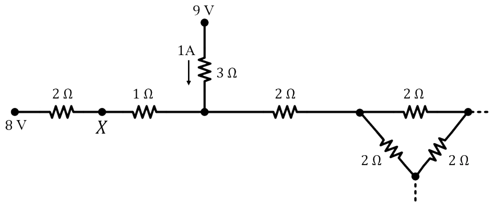
Full question on page 18 of the official paper (PDF)
Show answerHide answer
Key idea: The known current through the 3 Ω fixes the junction voltage, and then the rest of the network doesn't matter for node X.
Official answer: A
The 3 Ω resistor drops 1 \times 3 = 3 V, so the junction is at 9 - 3 = 6 V.
Node X has only two connections, so the current in from the 8 V node equals the current out to the junction:
Option (A). The resistors to the right of the junction only carry whatever current is left over there.
Learn the idea:
GATE 2025, Q.20
Networks, Signals and Systems1 markMCQ
A source of V is connected across a capacitor of admittance S, an inductor of S and a resistor of S, all in parallel, as in the figure. Which set of branch currents is correct?
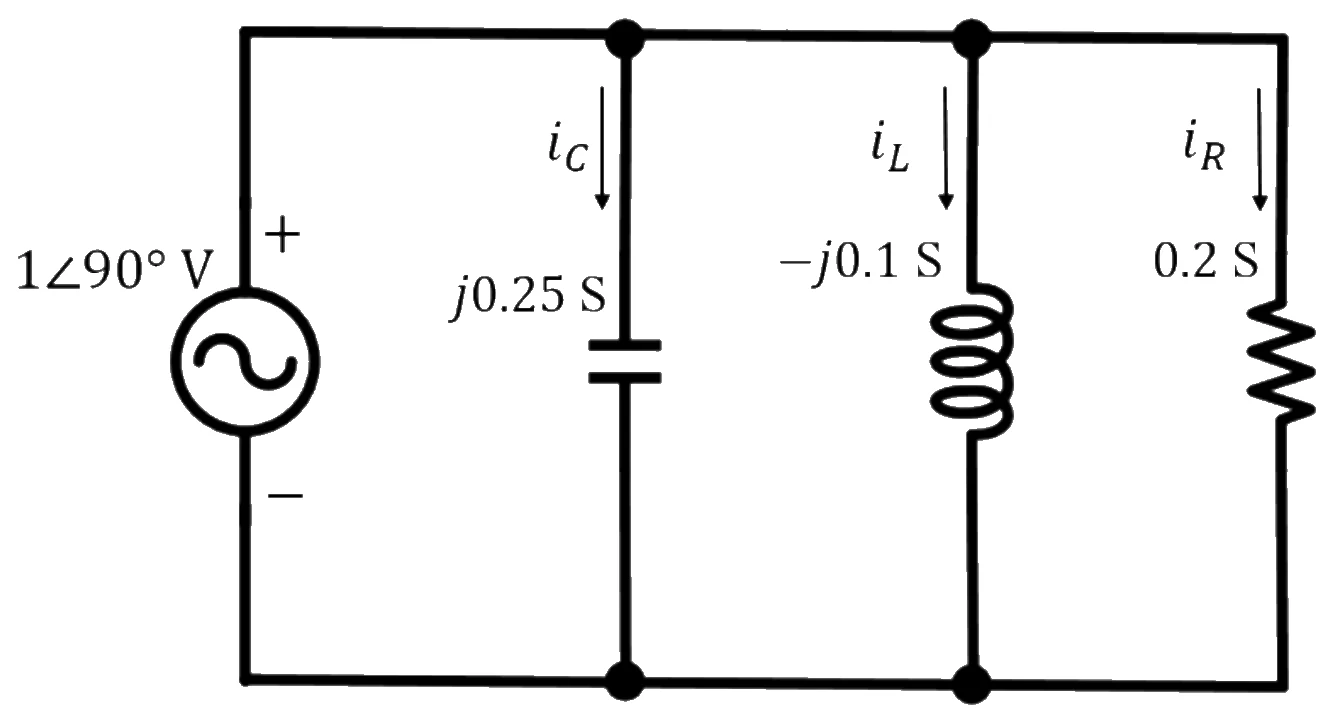
Full question on page 19 of the official paper (PDF)
Show answerHide answer
Key idea: With admittances, each branch current is I = YV: multiply, don't divide.
Official answer: A
Every branch has the full source voltage V = 1\angle 90° = j across it, so
Option (A). Option (B) divides by the admittances, as if they were impedances.
Learn the idea:
GATE 2025, Q.27
Networks, Signals and Systems1 markMSQ
has z-transform . Which statements are TRUE?
One or more options are correct.
Full question on page 26 of the official paper (PDF)
Show answerHide answer
Key idea: The DTFT is the z-transform on the unit circle, and the RoC can never contain a pole but may contain zeros.
Official answer: C and D
- (A) is false: x[n] = 2^n u[n] has X(z) = \frac{1}{1 - 2z^{-1}} for |z| > 2, but no DTFT.
- (B) is false: the RoC has no poles, but it can contain zeros. x[n] = \delta[n] - \delta[n-1] has X(z) = 1 - z^{-1}, with a zero at z = 1 inside its RoC.
- (C) is true: on the unit circle, X(e^{j\omega}) is the DTFT, and it converges there when the circle is in the RoC.
- (D) is true: X(z) = \alpha for every z, so the RoC is the whole plane.
Options (C) and (D).
Learn the idea:
GATE 2025, Q.38
Networks, Signals and Systems2 marksMCQ
has finite energy and a Fourier transform that is zero outside . It is sampled as with , where and , and passes through an ideal low-pass filter with cutoff and passband gain . What is the filter's output?
Full question on page 33 of the official paper (PDF)
Show answerHide answer
Key idea: Shifting the sampling instants changes where the samples are taken, not which signal they are samples of.
Official answer: A
The impulses sit at t = \tau + nT_s and carry f's own values there, f(\tau + nT_s). In frequency, the shifted impulse train is
The k = 0 copy is F(\omega)/T_s with no phase factor: the offset only multiplies the other copies by a phase. If the copies don't overlap, \omega_s > 2\omega_c, that is T_s < \pi/\omega_c, the filter keeps just the k = 0 copy and its gain T_s restores F(\omega). The output is f(t). Option (A).
Option (B) is the usual slip: the samples are taken later, but they are still samples of f(t), not of f(t - \tau).
GATE 2025, Q.39
Networks, Signals and Systems2 marksMCQ
An unknown linear time-invariant circuit, driven by V, feeds a branch of 5 Ω, a variable capacitor and 1 H in series, as in the figure. An ideal AC voltmeter across the branch reads 25 V RMS, and an ideal AC ammeter in it reads 5 A RMS. What should be?
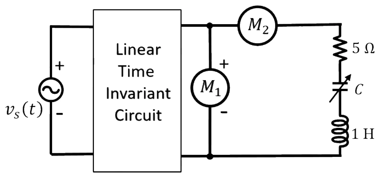
Full question on page 34 of the official paper (PDF)
Show answerHide answer
Key idea: The two meter readings give the branch's impedance magnitude without needing anything about the rest of the circuit.
Official answer: A
The branch has 25 V across it and 5 A through it, so
So the reactance is zero: the branch is at resonance at \omega = 200 rad/s.
Option (A). The unknown circuit doesn't matter, because the meters measure the branch directly.
Learn the idea:
GATE 2025, Q.40
Networks, Signals and Systems2 marksMCQ
Find the Z-parameter matrix, in ohms, of the two-port in the figure: from port 1, a 2 Ω series resistor, a 2 Ω shunt, a 2 Ω series resistor, a 2 Ω shunt, and a 2 Ω series resistor to port 2.
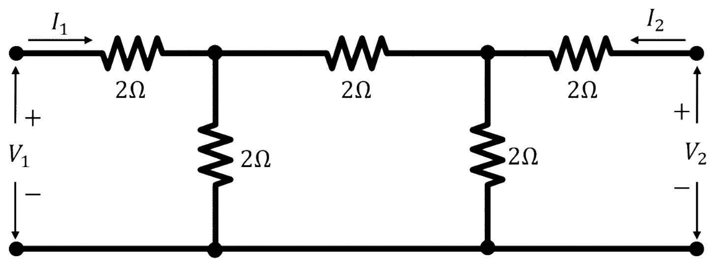
Full question on page 35 of the official paper (PDF)
Show answerHide answer
Key idea: Each Z-parameter is a ratio measured with the other port open, so the open port's series resistor carries no current.
Official answer: A
Call the two shunt nodes A (near port 1) and B. With port 2 open, the last 2 Ω carries nothing, so V_2 = V_B. From node A the network looks like 2 Ω in parallel with 2 + 2 = 4 Ω:
The current into node A splits so that V_A = \tfrac{4}{3} I_1, and the divider of 2 Ω and 2 Ω gives V_B = \tfrac{1}{2} V_A:
Z_{21} = \frac{V_2}{I_1} = \frac{2}{3}\ \OmegaThe network is symmetric and reciprocal, so Z_{22} = \tfrac{10}{3} and Z_{12} = \tfrac{2}{3}. Option (A).
Learn the idea:
GATE 2025, Q.55
Networks, Signals and Systems2 marksMSQ
is periodic with fundamental period , and with . Their Fourier series are and . Which statements are TRUE?
One or more options are correct.
Full question on page 47 of the official paper (PDF)
Show answerHide answer
Key idea: Compressing a signal in time shrinks its period and raises every harmonic's frequency, but leaves the weight of each harmonic unchanged.
Official answer: A and D
Substitute \alpha t for t in the series for f:
That is exactly the given form for y, so d_k = c_k: (A) is TRUE and (C) is FALSE. y repeats when \alpha t advances by T_0, so its fundamental period is T_0 / \alpha: (D) is TRUE and (B) is FALSE. Options (A) and (D).
Learn the idea:
GATE 2024, Q.21
Networks, Signals and Systems1 markMCQ
A causal, stable LTI system with impulse response gives output for input . The input is applied to another causal, stable LTI system with impulse response . What is the output?
Full question on page 18 of the official paper (PDF)
Show answerHide answer
Key idea: Stretching both signals in a convolution stretches the result by the same factor and scales its area.
Official answer: A
\int_{-\infty}^{\infty} x(0.5\tau)\,h\big(0.5(t - \tau)\big)\,d\tauSubstitute u = 0.5\tau, so d\tau = 2\,du:
Option (A).
GATE 2024, Q.24
Networks, Signals and Systems1 markMSQ
A causal discrete-time LTI system has . Which statements are true?
One or more options are correct.
Full question on page 21 of the official paper (PDF)
Show answerHide answer
Key idea: For a causal system, the poles decide stability, the zeros decide minimum phase, and h[0] = \lim_{z\to\infty} H(z).
Official answer: A, C and D
- (A) The poles \pm\frac{1}{3} are inside the unit circle, so the causal system is stable: true.
- (B) The zeros satisfy z^2 = -\frac{3}{2}, so |z| = \sqrt{1.5} \approx 1.22 > 1. Zeros outside the unit circle mean it isn't minimum phase: false.
- (C) h[0] = \lim_{z\to\infty} H(z) = 2: true.
- (D) Stable means h[n] \to 0: true.
Options (A), (C) and (D).
Learn the idea:
GATE 2024, Q.31
Networks, Signals and Systems1 markNAT
In the circuit in the figure, a 5 mA source and a 1 kΩ resistor carrying sit on the left node. A current-controlled voltage source of (positive on the right) joins it to the right node, which has a 1 kΩ resistor in series with a 2 mA source, and a 1 kΩ resistor carrying , all to the common bottom rail. What is , in mA?
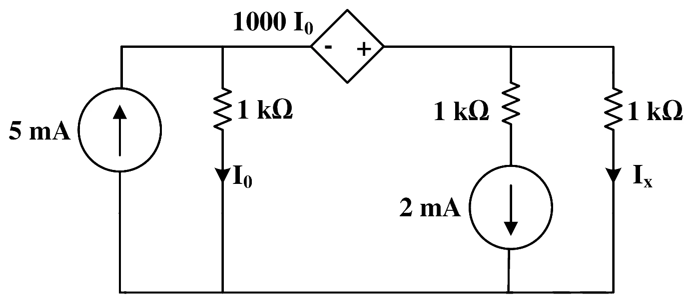
Answer format: mA, an integer
Full question on page 25 of the official paper (PDF)
Show answerHide answer
Key idea: The dependent source fixes the right node at the left node's voltage plus 1000\,I_0, so both node voltages are multiples of I_0.
Official answer: 2
With currents in mA and resistances in kΩ, the left node is at V_1 = I_0 volts, and the dependent source adds 1000\,I_0 A = I_0 (mA) volts, so the right node is at V_2 = 2I_0 and I_x = V_2 / 1 = 2I_0.
Current into the right node is what the left node doesn't send through its 1 kΩ, and it leaves through the 2 mA branch and I_x:
Learn the idea:
GATE 2024, Q.32
Networks, Signals and Systems1 markNAT
In the circuit in the figure, a 5 A source with 2 Ω across it feeds a 3 H inductor into a node with 4 Ω to ground. The switch S, open for a long time, closes at and puts a second 4 Ω across that node. What is the time constant for , in seconds?
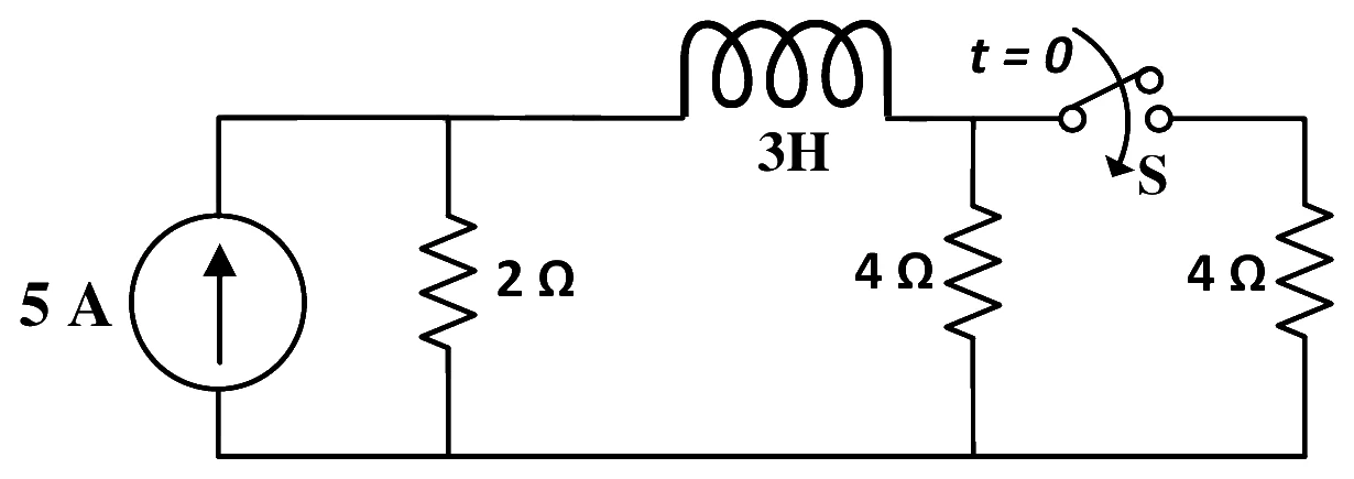
Answer format: Seconds
Full question on page 25 of the official paper (PDF)
Show answerHide answer
Key idea: The time constant is L over the resistance the inductor sees with the independent source turned off.
Official answer: 0.75
With the 5 A source open-circuited, the inductor sees the 2 Ω on one side and the two 4 Ω resistors in parallel on the other, all in series:
Learn the idea:
GATE 2024, Q.44
Networks, Signals and Systems2 marksMCQ
The figure shows , a downward triangle between and with minimum , and , an upward triangle between and with peak 1. If is the Fourier transform of , which is the Fourier transform of ?
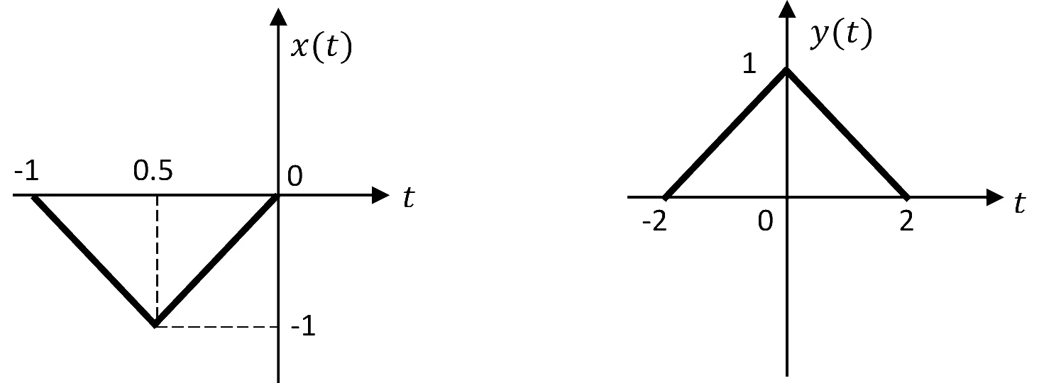
Full question on page 34 of the official paper (PDF)
Show answerHide answer
Key idea: A question given marks to all scores full marks for every candidate, whatever they answered.
Official answer: Marks to all
The final key awards marks to all for this question and doesn't say why, so we don't pick an option.
The method it tests: write y as a flipped, stretched and shifted copy of x, then apply the scaling and shift properties, x(at - b) \leftrightarrow \frac{1}{|a|}X\!\left(\frac{f}{a}\right)e^{-j2\pi f b/a}. One likely reason for the ruling is the figure: the tick under the minimum of x(t) is labelled 0.5, though the minimum sits between -1 and 0.
Ruling in the key: The final key gives marks to all (MTA) for this question: every candidate received its 2 marks.
Learn the idea:
GATE 2024, Q.48
Networks, Signals and Systems2 marksMCQ
is sampled at 15 Hz. The sampled signal passes through an LTI system with , giving . What is ?
Full question on page 36 of the official paper (PDF)
Show answerHide answer
Key idea: A question given marks to all scores full marks for every candidate, whatever they answered.
Official answer: Marks to all
The final key awards marks to all for this question and doesn't say why, so we don't pick an option.
The method it tests: sampling at 15 Hz copies the 4 Hz tone to 15k \pm 4 Hz, the filter passes a narrow band round 19 Hz with its own phase shift, and the output is the 19 Hz copy. One likely reason for the ruling is that the answer's amplitude and phase depend on how the impulse sampling and the filter's gain are normalised, which the question leaves open.
Ruling in the key: The final key gives marks to all (MTA) for this question: every candidate received its 2 marks.
Learn the idea:
GATE 2024, Q.56
Networks, Signals and Systems2 marksMSQ
For which radian frequencies does have a period of 40?
One or more options are correct.
Full question on page 43 of the official paper (PDF)
Show answerHide answer
Key idea: \cos(\Omega n) repeats after N samples when \Omega N is a whole number of turns, 2\pi m.
Official answer: A and D, or A, C and D
Write \Omega = 2\pi m/N in lowest terms; the fundamental period is then N:
- 0.15\pi = 2\pi \cdot \frac{3}{40}: fundamental period 40.
- 0.225\pi = 2\pi \cdot \frac{9}{80}: period 80, and 40 is not a period.
- 0.3\pi = 2\pi \cdot \frac{3}{20}: fundamental period 20, so 40 is a period but not the fundamental one.
- 0.45\pi = 2\pi \cdot \frac{9}{40}: fundamental period 40.
If "a period of 40" means the fundamental period, the answer is (A) and (D); if it means any period, (C) qualifies too. The key accepts both: A and D, or A, C and D.
GATE 2024, Q.59
Networks, Signals and Systems2 marksNAT
For an -point sequence, is its -point DFT. Let . For , what is ?
Answer format: An integer
Full question on page 44 of the official paper (PDF)
Show answerHide answer
Key idea: Applying the DFT twice gives N times the time-reversed sequence, so four times gives N^2 times the original.
Official answer: 112
So y[n] = 16\,x[n], and Y[0] = \sum_n y[n] = 16(1 + 2 + 1 + 3) = 112.
GATE 2024, Q.60
Networks, Signals and Systems2 marksNAT
In the two-port in the figure, port 1 connects through 2 Ω to a node that is wired straight to port 2. From that node a shunt branch runs through 4 Ω and a dependent voltage source (negative at the top, positive at the bottom) to the common rail. What is , in siemens?
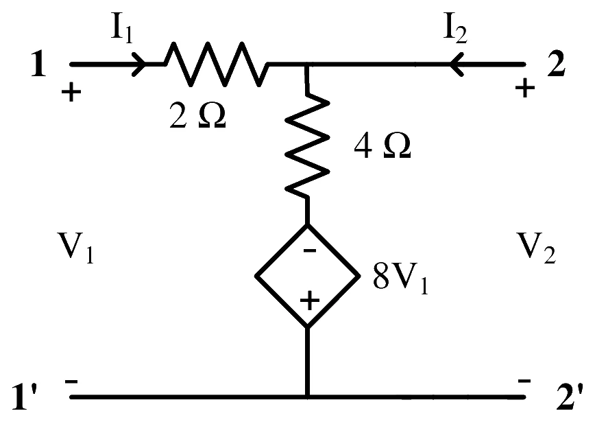
Answer format: Siemens
Full question on page 45 of the official paper (PDF)
Show answerHide answer
Key idea: Y_{21} = I_2/V_1 with port 2 short-circuited.
Official answer: 1.5
With port 2 shorted the node is at 0 V, so I_1 = V_1/2. The source holds the bottom of the 4 Ω at -8V_1, so the shunt branch draws \frac{0 - (-8V_1)}{4} = 2V_1 from the node. KCL at the node:
Learn the idea:
GATE 2024, Q.62
Networks, Signals and Systems2 marksNAT
In the network in the figure, a 50 V source feeds the load through two parallel paths: 2 Ω then 3 Ω, with across the 3 Ω (positive at the load end); and a dependent voltage source (positive towards the load) then 2 Ω. What value of , in ohms, receives maximum power?
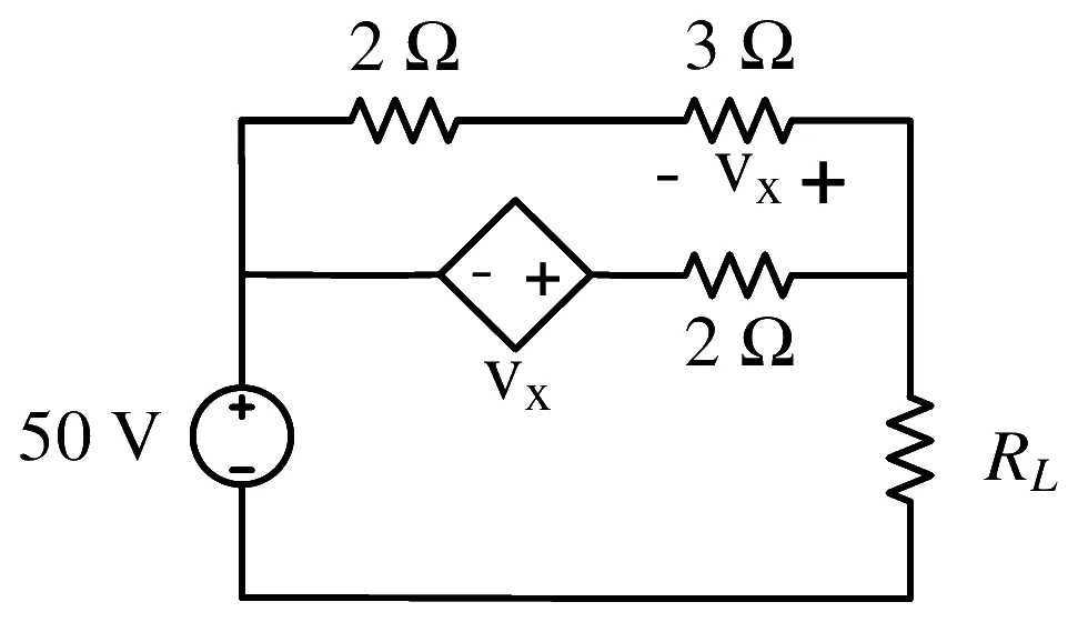
Answer format: Ohms
Full question on page 45 of the official paper (PDF)
Show answerHide answer
Key idea: With a dependent source, find the Thevenin resistance by turning off the independent source and driving the terminals with a test voltage.
Official answer: 2.5
Short the 50 V source and apply a test voltage V across the load terminals. The top path is 5 Ω, carrying V/5, and its 3 Ω takes v_x = \tfrac{3}{5}V.
In the lower path the dependent source lifts its right end to v_x = 0.6V, so its 2 Ω carries (V - 0.6V)/2 = 0.2V. The total test current is 0.2V + 0.2V = 0.4V:
Learn the idea:
GATE 2023, Q.18
Networks, Signals and Systems1 markMCQ
A series circuit has a quality factor of 1000 at a centre frequency of rad/s. What are possible values of , and ?
Full question on page 12 of the official paper (PDF)
Show answerHide answer
Key idea: For a series RLC, \omega_0 = 1/\sqrt{LC} and Q = \omega_0 L / R.
Official answer: D
Every option has L = 1\ \muH and C = 1\ \muF, so \omega_0 = 1/\sqrt{10^{-12}} = 10^6 rad/s, as required. Then
Option (D).
Learn the idea:
GATE 2023, Q.26
Networks, Signals and Systems1 markMCQ
A system has input and output . The system is
Full question on page 18 of the official paper (PDF)
Show answerHide answer
Key idea: Causal means y(t) uses no input later than t; time invariant means a delayed input gives the same output, delayed.
Official answer: B
Causality: e^t > t for every t, so y(t) always uses the input at a later time. At t = 0, y(0) = x(1). The system is non-causal.
Time invariance: delaying the input by t_0 gives x(e^t - t_0), but delaying the output gives y(t - t_0) = x(e^{t - t_0}). These differ, so the system is time varying. Option (B).
GATE 2023, Q.28
Networks, Signals and Systems1 markMCQ
What is the Fourier transform of ? (Note: .)
Full question on page 19 of the official paper (PDF)
Show answerHide answer
Key idea: Complete the square in the exponent, then use the given integral.
Official answer: C
A quick check: X(0) must equal \int x(t)\, dt = \sqrt{\pi}, which rules out (B), and (A) grows with \omega. Option (C).
GATE 2023, Q.29
Networks, Signals and Systems1 markMCQ
Match each signal type with its spectral characteristics. Signal types: (i) continuous, aperiodic; (ii) continuous, periodic; (iii) discrete, aperiodic; (iv) discrete, periodic. Spectral characteristics: (a) continuous, aperiodic; (b) continuous, periodic; (c) discrete, aperiodic; (d) discrete, periodic.
Full question on page 20 of the official paper (PDF)
Show answerHide answer
Key idea: Periodic in one domain means discrete in the other, and discrete in one domain means periodic in the other.
Official answer: B
- (i) Continuous, aperiodic: the Fourier transform, continuous and aperiodic, (a).
- (ii) Continuous, periodic: the Fourier series, discrete lines, aperiodic, (c).
- (iii) Discrete, aperiodic: the DTFT, continuous and periodic in 2\pi, (b).
- (iv) Discrete, periodic: the DFS, discrete and periodic, (d).
Option (B).
Learn the idea:
GATE 2023, Q.32
Networks, Signals and Systems1 markNAT
In the circuit in the figure, what is the current flowing through the 200 Ω resistor, in mA?
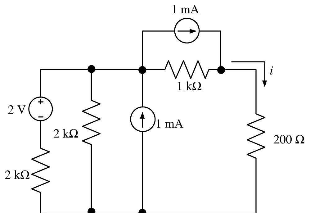
Answer format: mA, rounded off to two decimal places
Full question on page 22 of the official paper (PDF)
Show answerHide answer
Key idea: Two unknown node voltages: write KCL at each, working in volts, mA and kΩ.
Official answer: 1.30 to 1.40
Call the top-left node A and the node above the 200 Ω resistor B. In mA and kΩ, KCL at A (the 1 mA into A from below and the 1 mA out of A to B cancel):
KCL at B, with the 1 mA source feeding it:
So V_A = (1 + V_B)/2, and 5.5\,V_B = 1.5 gives V_B = 0.2727 V. Then i = V_B / 0.2\ \text{k}\Omega = 1.36 mA.
Learn the idea:
GATE 2023, Q.33
Networks, Signals and Systems1 markNAT
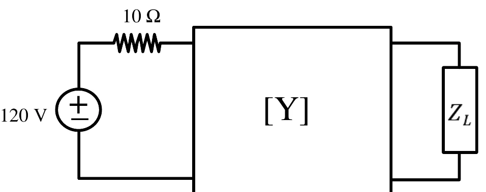
For the two-port network in the figure, S. It is driven by a 120 V source through 10 Ω at port 1. What load impedance , in Ω, takes the maximum power?
Answer format: Ohms, rounded off to the nearest integer
Full question on page 22 of the official paper (PDF)
Show answerHide answer
Key idea: Maximum power needs Z_L equal to the Thevenin impedance seen at port 2, with the source shorted.
Official answer: 80
With the source shorted, port 1 sees I_1 = -V_1/10, so -0.1V_1 = 0.02V_1 - 0.01V_2, which gives V_1 = V_2/12. Then
So Z_{th} = 1/0.0125 = 80 Ω, and Z_L = 80 Ω. Equivalently, Y_{out} = Y_{22} - Y_{12}Y_{21}/(Y_{11} + 0.1). Answer: 80.
Learn the idea:
GATE 2023, Q.35
Networks, Signals and Systems1 markNAT
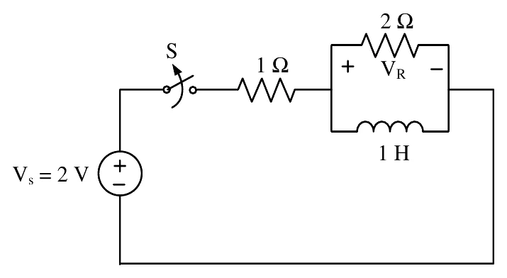
In the circuit in the figure, a 2 V source drives, through switch S and 1 Ω, a 2 Ω resistor in parallel with a 1 H inductor. S was closed for a long time and is opened at . What is the maximum magnitude of the voltage across the 2 Ω resistor, in volts?
Answer format: volts, rounded off to the nearest integer
Full question on page 23 of the official paper (PDF)
Show answerHide answer
Key idea: The inductor current can't change instantly, and once S opens it has nowhere to go but the 2 Ω resistor.
Official answer: 4
Before t = 0 the inductor is a short, so V_R = 0 and the whole current, 2/1 = 2 A, flows through the inductor.
After S opens, the inductor and the 2 Ω resistor form a loop, and the 2 A must flow through the resistor: |V_R(0^+)| = 2 \times 2 = 4 V. It then decays as 4e^{-2t}, so the maximum magnitude is 4 V.
GATE 2023, Q.44
Networks, Signals and Systems2 marksMCQ
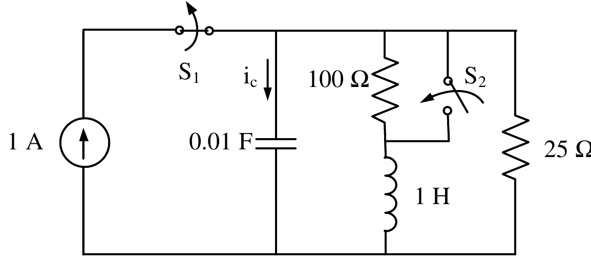
In the circuit in the figure, switch was closed and was open for a long time. At , is opened and is closed, simultaneously. shorts the 100 Ω resistor that is in series with the 1 H inductor. What is , in amperes?
Full question on page 31 of the official paper (PDF)
Show answerHide answer
Key idea: Find the capacitor voltage and inductor current before switching; both carry over to t = 0^+.
Official answer: B
Before t = 0 the capacitor is open and the inductor a short, so the 1 A splits between the 100 Ω branch and the 25 Ω resistor:
At t = 0^+ the source is gone, v_C = 20 V and i_L = 0.2 A. With the 100 Ω shorted, the inductor still carries 0.2 A, and the 25 Ω carries 20/25 = 0.8 A. The capacitor supplies both, so the current down into it is i_C(0^+) = -(0.2 + 0.8) = -1 A. Option (B).
Learn the idea:
GATE 2023, Q.46
Networks, Signals and Systems2 marksMCQ
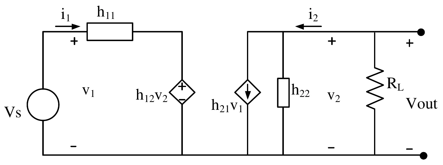
The h-parameter model of a two-port network is shown in the figure, driven by and loaded by . What is the condition for the maximum small-signal voltage gain ?
Full question on page 33 of the official paper (PDF)
Show answerHide answer
Key idea: A question given marks to all scores full marks for every candidate, whatever they answered.
Official answer: Marks to all
The key awards marks to all for this question and doesn't say why, so we don't pick an option.
The idea behind it: with V_s driving port 1 directly, the gain of an h-parameter two-port is -h_{21}R_L / \left(h_{11} + \Delta h\, R_L\right) with \Delta h = h_{11}h_{22} - h_{12}h_{21}, so a large h_{21} and small h_{11}, h_{12} and h_{22} raise it. One likely reason for the ruling is the figure: it labels the output source h_{21}v_1 where the h-parameter model has h_{21}i_1, and with h_{11} = 0 and h_{12} = 0 the input current isn't set by V_s at all.
Ruling in the key: The key gives marks to all (MTA) for this question: every candidate received its 2 marks.
GATE 2023, Q.47
Networks, Signals and Systems2 marksMCQ
A discrete-time periodic signal has period and DTFS , with , , , and . What is ?
Full question on page 34 of the official paper (PDF)
Show answerHide answer
Key idea: \sum_n x[n] e^{-jk2\pi n/N} = N a_k, so write the sine as two exponentials.
Official answer: A
\sin\frac{4\pi n}{5} = \frac{e^{j4\pi n/5} - e^{-j4\pi n/5}}{2j}\sum_n x[n] e^{-j2(2\pi n/5)} = 5a_2 = 10j, and \sum_n x[n] e^{+j2(2\pi n/5)} = 5a_{-2} = 5a_3 = -10j. So
Option (A).
Learn the idea:
GATE 2023, Q.48
Networks, Signals and Systems2 marksMCQ
An input with DTFT is passed through an LTI system with frequency response . What is the output ?
Full question on page 34 of the official paper (PDF)
Show answerHide answer
Key idea: Multiply the two polynomials in e^{-j\Omega}; each power e^{-jk\Omega} is a \delta[n-k].
Official answer: C
The e^{-j3\Omega} term collects 2 from X and +\tfrac{1}{2} from (-e^{-j\Omega})(-\tfrac{1}{2}e^{-j2\Omega}). So y[n] = \delta[n] - \delta[n-1] - \tfrac{1}{2}\delta[n-2] + \tfrac{5}{2}\delta[n-3] - \delta[n-5]. Option (C).
Learn the idea:
GATE 2023, Q.49
Networks, Signals and Systems2 marksMCQ
is passed through an LTI system with impulse response . What is the output?
Full question on page 35 of the official paper (PDF)
Show answerHide answer
Key idea: \sin Wt/(\pi t) is an ideal low-pass of height 1 and cut-off W; squaring it makes a triangle in frequency.
Official answer: A
\dfrac{\sin Wt}{\pi t} transforms to a rectangle of height 1 on |\omega| < W. Its square transforms to \tfrac{1}{2\pi} times the rectangle convolved with itself: a triangle of peak \tfrac{2W}{2\pi} = \tfrac{W}{\pi}, reaching zero at |\omega| = 2W. Times \pi, the peak is W:
Multiplying by \cos 10Wt shifts half of it to each of \pm 10W: H(\omega) = \tfrac{1}{2}[T(\omega - 10W) + T(\omega + 10W)]. At \omega = 10.5W, 0.5W from the centre:
H is real and positive, so there is no phase shift: y(t) = 10 \cdot \tfrac{3W}{8}\cos(10.5Wt) = \tfrac{15W}{4}\cos(10.5Wt). Option (A).
GATE 2023, Q.50
Networks, Signals and Systems2 marksMCQ
and are band-limited signals, each with bandwidth rad/s. In the figure, . What Nyquist sampling frequency, in rad/s, is required to sample ?
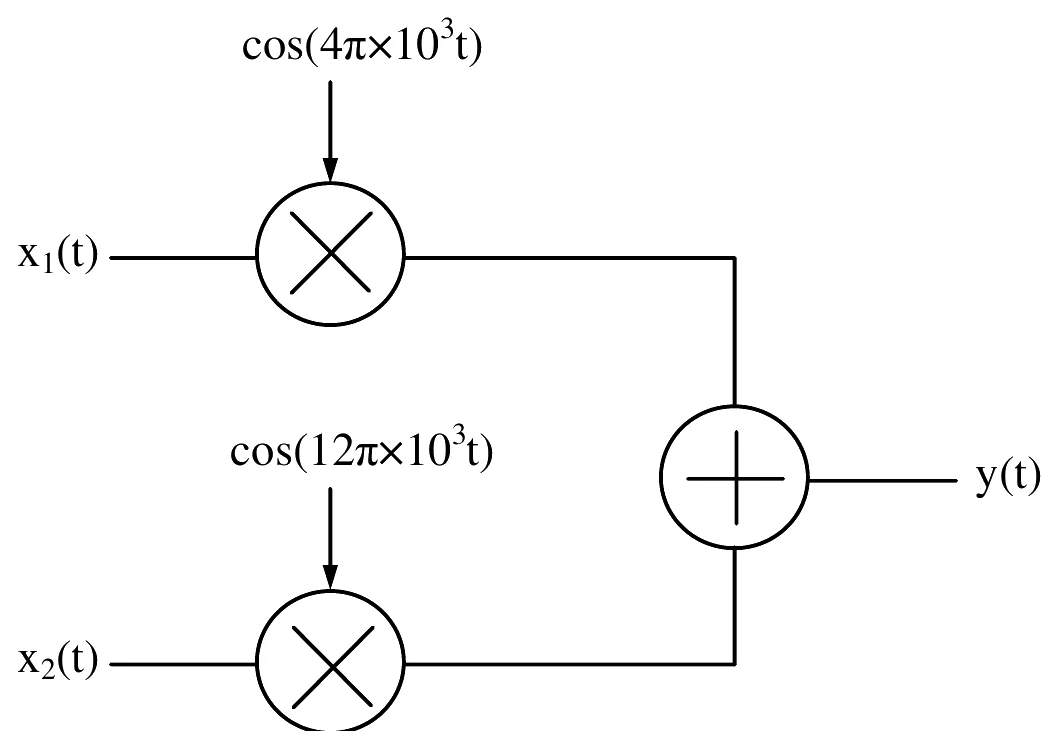
Full question on page 36 of the official paper (PDF)
Show answerHide answer
Key idea: Find the highest frequency in y(t) and double it.
Official answer: D
Multiplying by a cosine shifts the spectrum to the carrier. x_1 reaches 4\pi + 4\pi = 8\pi \times 10^3 rad/s, and x_2 reaches 12\pi + 4\pi = 16\pi \times 10^3 rad/s. The highest frequency is 16\pi \times 10^3, so
Option (D).
Learn the idea:
GATE 2023, Q.58
Networks, Signals and Systems2 marksNAT
Let , and let be as in the figure. For , what is ?
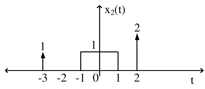
Answer format: rounded off to the nearest integer
Full question on page 42 of the official paper (PDF)
Show answerHide answer
Key idea: The area of a convolution is the product of the two areas.
Official answer: 15
\int y\, dt = \left(\int x_1\, dt\right)\left(\int x_2\, dt\right)x_1 is a pulse of height 1 and width 3, area 3. x_2 has area 1 + (1 \times 2) + 2 = 5: the two impulses and the pulse. So \int y\, dt = 3 \times 5 = 15.